Tuesday, December 20, 2016

Equidistribution of ornaments across your Christmas tree's lateral surface area


Introduction


I have been learning a lot of math lately. I now know more math than I ever fathomed I would, more than I knew there was out there to learn. This is great, and has given me a (much improved) altered view of the world. I now see and approach everything through mathematical lenses. Even the most mundane or routine day-to-day tasks can benefit from this outlook. For example: Decorating the Christmas tree.


The problem


It seems like just about everybody is concerned with ensuring the ornaments on the Christmas tree are placed evenly, and there is no bunching or grouping of ornaments on one side of the tree versus the other. This is usually achieved by eyeballing it; a totally subjective experience. Well, this concern came up again this year as it often does, except this time, I had my mathematical lenses...

Lets say you want to achieve near-perfect spacing of the ornaments on your Christmas tree, and all you have is a ruler, or maybe a carpenters square (apparently Sheldon does this on The Big Bang Theory, as my friend explained to me while I was writing this).

You can figure out the number of ornaments you have, since you can count them, so how do you know how far apart to space each ornament?


The strategy


Thinking about it, it seems the simplest way would be to divide the number of ornaments you have over the area of the ornament-hanging real estate, and we would get a result in terms of 1 ornament per X feet^2. I think we can work with that.


Surface area of the ornament-space of a standard tree


The formula for calculating the surface areas is well know for a wide variety of shapes. Given a shape, we can just google for the formula. Take a gander at your Christmas tree, what shape does it remind you of? Well, its conical. We can generalize a Christmas tree to the shape of a cone:

Now when I first did this, the result I got just didn't seem right, I was getting a result of ~91.5 square feet. There was no way my tree was exposing 91 square feet of ornament space! Well, the surface area of a cone includes the base, of course, and not too many people hang Christmas ornaments underneath of the tree. Whoops!

So after some googling, I found out that the surface area of the slanted part of the cone is called the Lateral Surface Area of a cone.


The formula


So all that is required is for you measure the radius of your Christmas tree, the height from the base, plug those numbers into the above formula, and that returns the surface area in square units. The units are whatever units you put into the formula, typically inches.

Note: The radius (r) is measured from the trunk out to the end of the branches at the base. The height (h) is measured from the base to the top. Do not measure from the floor to the tip, as this will include the length of the trunk, and since the surface area per unit of height is greatest at the bottom, this will throw your surface area calculation off by a lot.

Then, dividing the number of ornaments you have by the surface area gives you the number or ornaments per square unit. You can then at this point, cut out a square piece of paper to match the area that one ornament should occupy. Do this four times to make four squares. If you have thicker paper or card stock, use that. Tape the four squares together, two on top, two on bottom, offset by half a square, like seen here:


This will be your template. This gives you a frame of reference, so you can align ornaments in reference to ones already hung. You can even draw and cut out circles in the center to obviate any need for guesswork or eye-balling their placement.


Tuesday, December 6, 2016

Javascript inside svg?


Readers might or might not be aware that an SVG file is really just an XML document. And yes, as you suspected, it allows javascript and viewers are expected to support it, as if that was a sane thing to do. I'm sure this kind of thing is just about as smart as it sounds, in fact I believe I first discovered this foolhardy feature in a forum post displaying some obfuscated javascript inside an svg tag and it was in reference to a XSS attack that was leveraging Facebook.

I had to run a quick test, to see if it was true. I typed the following text to a file with the extension .svg, and the file opened up in internet explorer:

<svg version="1.1" xmlns="http://www.w3.org/2000/svg">
  <script type="text/javascript">alert('Hax!');</script>
</svg>

Now, I use chrome and keep my internet explorer locked down. I don't know what comes up on other people's machines, but at least mine prompted me, asking if I wanted to allow blocked ActiveX controls. However, chrome runs it no problem and without bothering to prompt me. Joy.

I don't know about you, but I don't want my images to be able to prompt me. It is not hard to imagine a scenario where an svg being served up by a server could contain javascript attempting to access the user's cookies for that server.

While the black hats of the world are busy thinking of new (ab)uses of this technology, it is interesting to consider the creative aspects. If an SVG contains only a JavaScript loop that draws the image, can the image be said to draw itself? Clearly, not in the most literal sense, as rather the image is interpreted, and it is the interpreter that does the drawing. Yet in some sense it does draw itself. At any rate, it can certainly create some intense images in only 1 kB or so.

Naturally, my mind jumped to the idea of making a prime number sieve, as a way to make a complex drawing with only a single loop. After a little bit of playing, I had something that looks a lot like Sieves of Chaos. After a little more tweaking, I had something that looks almost identical to Sieves of Chaos.


I encourage you to try it out for yourself; just copy and paste the below code to Notepad++, and save with a .SVG extension. You will notice the image is 8096 units wide. If your machine can handle it, there is no reason the width couldn't be extended. For some machines, this may already be a crippling number. The effect is very nice, and I even created a spanning desktop background out of it.


<svg version="1.1" xmlns="http://www.w3.org/2000/svg">
 <script type="text/javascript"><![CDATA[
  var width=8096;
  var height=900;
  var ns="http://www.w3.org/2000/svg";
  var svg = document.getElementsByTagName('svg')[0];
  svg.setAttribute("width", width);
  svg.setAttribute("height", height);
  
  var rect = document.createElementNS(ns, 'rect');
  rect.setAttribute("height", height);
  rect.setAttribute("width", width);
  rect.style.fill = "black";
  svg.appendChild(rect);

  for (var b = 2; b < width; b += 1)
  {
   for (var a = 1; a < width; a += b*2)
   {
    var cir = document.createElementNS(ns, 'circle');
    cir.setAttribute("shape-rendering", "geometricPrecision");
    cir.setAttribute("stroke-opacity", "0.07");
    cir.setAttribute("r",  b);
    cir.setAttribute("cx", a+b);
    cir.setAttribute("cy", height/2);
    cir.style.stroke = "red";
    cir.style.strokeWidth = "1";
    cir.style.fill = "none";
    svg.appendChild(cir);
   }
  }
 ]]></script> 
</svg>

Blogger is wise, and does not accept .svg files. There is hope. Here is the .png image that I am using for my background (below). Feel free to use that or render your own with the above code. Be warned, the below png file is 3 MB.


Thursday, November 24, 2016

EntropyGlance

Entropy at a glance


In a hurry? Skip straight to the C# source code - EntropyGlance; Entropy at a glance - A C# WinForms project - https://github.com/AdamWhiteHat/EntropyGlance


So I wrote an file entropy analysis tool for my friend, who works in infosec. Here it is, hands-down the coolest feature this tool offers is a System.Windows.Forms.DataVisualization.Charting visualization that graphs how the entropy changes across a whole file:


This application provides both Shannon (data) entropy and entropy as a compression ratio.
Get a more intuitive feel for the overall entropy at a glance with by visualizing both measures of entropy as a percentage of a progress bar, instead of just numbers.


   However, for those who love numbers, standard measures of entropy are also given as well. Information entropy is expressed both as the quantity of bits/byte (on a range from 0 to 8), and as the 'normalized' value (range 0 to 1). High entropy means it the data is random-looking, like encrypted or compressed information.
   The Shannon 'specific' entropy calculation makes no assumptions about the type of message it is measuring. What this means is that while a message consisting of only 2 symbols will get a very low entropy score of 0.9/8, a message of 52 symbols (the alphabet, as lower case first, then upper) repeated in the same sequence one hundred times would be yield a higher-than-average score of 6/8.
   This is precisely why I included a compression ratio as a ranking of entropy that is much closer to notion of entropy that takes into account repeated patterns or predictable sequences, in the sense of Shannon's source coding theorem.


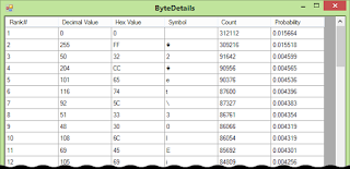
Dive deep into the symbol distribution and analysis. This screen gives you the per-symbol entropy value and the ability to sort by rank, symbol, ASCII value, count, entropy, and hex value:


As always, the C# source code is being provided, hosted on my GitHub:
EntropyGlance; Entropy at a glance - A C# WinForms project - https://github.com/AdamWhiteHat/EntropyGlance


Wednesday, September 21, 2016

RC4 stream cipher variants and visualization of table permutation state


Here, I present some work I have been doing on two RC4 stream cipher variants. The first variant, as seen below, I wrote to help me visualize and understand what the RC4 tables was doing, and help me understand its properties.

Identity Permutation

The class that contains it is called SimpleTable and is exactly that; The simplest R4C implementation possible. It is notable in the fact that it does not use key scheduling at all, and its starting state is that of the Identity Permutation. The identity permutation is where the value at index zero equals zero, the value at index one is one, and so on. An easy way to remember what the Identity Permutation is, just recall the notion of a Multiplicative Identity (which is 1), where by multiplying a number N by the Multiplicative Identity gives you back the value of N, also known as the identity. Similarly, the Identity Permutation of an array A just gives you A. This is the trivial permutation. That is, there is no permuting of the array at all!

Anyways, this is done to see the perfectly ordered state, and how each round effects that state. In this way, we can visually check for the avalanche effect. In order to visualize the table, i just assign each value 0 to 255 a different shade of grey (I also have a rainbow-colored option that might be easier to tell apart similar values). At each step I create a Bitmap by looping through the table. Below, you can find an animated GIF of the first 100 steps of this cipher being applied to the identity permutation:


Notice how it takes a while to get going, and the first several values don't move much at all. After 256 steps, or one round, the cursor arrives back at index zero. Because the location of the first several values have not moved much or at all, we can clearly see that a mere 256 steps is insufficient at permuting the state enough to avoid leaking the first part of your key. Therefore it it is vital to permute the table for several rounds (256 steps per round) before you start using the stream.

Wired Equivalent Protocol

As some of you may know, WEP used RC4 with a weak key schedule. The key is spread out over 256 bytes using the following approach:


j = (j + table[i] + key[i mod keylength]) % 256;
SwapValues(table[i], table[j]);


and then it began streaming bytes from the table. Typically a nonce is concatenated to the key. Every time the table is set up and/or the nonce changes, some information about the key is leaked. Obviously a more secure procedure would use a hash of the key and the nonce, instead of the plain-text key, and to toss away the first 1024 bytes or so.

Cycle Length

Because each step in an RC4 cipher is a permutation, there is a limit to the number of unique bytes that can be produced before it begins repeating. This is called the permutation cycle. The length of the permutation cycle depends on the exact starting state, but we can get an upper bound.

Since there are 256 elements in the array, and two indices into the array (i and j), there is a maximum of
256! * 256^2 = 5.62 * 10^512 = 2^1700
possible states. That's 4.6 * 10^488 yottabytes!

This is the maximum possible states, however, and other starting states could have less. If the RC4 algorithm performed as a random permutation (which it does not, it performs worse), the cycle length would be half of the theoretical maximum above. Luckily the number above is so vast, that even some faction of it is still so many bytes that all of humanity has never and likely will never have that much total storage.

One thing to watch out for, however is something called Finney States. If an RC4 is started in one of these Finney States, the length of the cycle is much, much reduced. The chance of randomly generating one of these starting states, however, is VERY, very low.

Strengthening RC4

As stated, and visualized, above, it is vital to permute the table for several rounds (at 256 steps per round) after the key schedule, discarding the bytes, before you start using the stream. Also, it would be foolish to use the actual bytes of the key for permuting the starting state. It would be instead better to use a hash of the key + nonce or a key derivation function from the key instead the actual value of the key itself.

Another idea is, after shuffling the table enough rounds to hide the key, scramble the table an additional number of rounds, that value being some function of the key. This increases the possible starting states by whatever your range is.

In the classic RC4, each step would return one byte. The number of steps taken before returning each byte is configurable in my implementation.

Memory hardening

Check out the experimental branch for a memory hardened version. It stores the key class in memory, with the key XORed with a one-time pad, and then is protected in memory from access with the System.Security.Cryptography.ProtectedMemory class.

Other uses

The pseudo-random byte stream from the RC4 table is deterministic. Therefore if two remote computers with a shared secret, both computers can independently set up an RC4 table with exactly the same starting state and will get the same sequence of bytes which would be difficult to guess, given just the stream of bytes. If the plain text is XORed by the pseudorandom byte stream, then it can be decrypted by XORing it by the same byte steam.

The project includes 2 variants: 1) A simple table with a method to visualize the permutation state of the table and the avalanche effect as a bitmap 2) A more serious attempt at a secure implementation.


NOTE: THIS HAS NOT BEEN CRYPTO-ANALYZED AND PROBABLY NOT ACTUALLY SECURE, SO DO NOT TRUST IT!

Screenshots


Source code

Here is the GitHub page to the project (master branch).
Or just directly download the Zip file (experimental branch).


Tuesday, August 16, 2016

Lorenz Chaos Attractor


This project was inspired by one of Daniel Shiffman's 10 minute coding challenge YouTube videos, The Lorenz Attractor in Processing.


        dX = ((A * y)  -  (A * x)) * time;
        dY = ((B * x) -y -(x * z)) * time;
        dZ = ((x * y)  -  (c * z)) * time;

So it turns out this it not too terribly exciting. While its true that adjusting the starting values by a small amount change the behavior, if you go much outside the values its currently set for, you will end up with a pattern that quickly degenerates to a single, boring point. Personally, I was hoping for a more chaotic system. You might notice I am not using the 3rd point. I have yet to find a 3D drawing library that I like, though I need one for visualizing other projects. Anyways, since this was an experiment, I did the pragmatic thing and just made it 2D since I already knew how to do that.

Here is the result:


GitHub project

It wanted to draw the pattern very small, so I had to scale up the image by multiplying each number by some scale number.

One possibly useful idea is to use the cosine of the tangent of each number. This has the effect of canceling out the spiral and spreading the numbers out over a field. If you use just the tangent, you get a gradient from the top left corner. Perhaps you could use this as a pseudo-random noise source.


public static void TanCos(Lorenz system)
{
        system.x = 16 * (decimal)Math.Tan(Math.Cos((double)system.x));
        system.y = 16 * (decimal)Math.Tan(Math.Cos((double)system.y));
}

public static void Tan(Lorenz system)
{
        system.x = 6 * (decimal)Math.Tan((double)system.x);
        system.y = 6 * (decimal)Math.Tan((double)system.y);
}